How to Choose the Right SWAS Configuration for Your Plant
.jpg?width=1135&height=780&rmode=crop)
Sentry Product Suite
The technical design specification is the first step in designing a steam and water analysis system (SWAS) that operates accurately, reliably and safely for your plant’s conditions.
Understanding the different possible configurations when designing your SWAS can help you choose one that will maximize efficiency and output while protecting plant assets, operators and the environment.
A well-written SWAS specification will include specific equipment details such as materials of construction, performance specs and ratings. The spec should also address considerations like vibration, wear, corrosion or other performance issues. SWAS specifications that are too broad will not identify equipment that will perform well in the application.
There are several industry guidelines (such as EPRI, ASTM D5540, ASME PTC 19.11, VGB and IAPWS) that can help you design and operate a SWAS. While most are very specific about the sample conditioning hardware, they often don’t detail the arrangement or design of the racks, panels and ancillary equipment associated with the steam and water analysis system package. Knowing how to mount the conditioning equipment with utilities (water, drains, signals and electrical) is critical for an easy-to-use and operate panel. Understanding these configurations will help you create well-designed specifications that will deliver representative steam and water samples.
SWAS LAYOUT AND DESIGN CONFIGURATIONS
Traditional Free-Standing Rack
Many specifications include a free-standing rack that can be mounted as an island in an existing building, retrofit to available space, installed in an environmentally controlled and stand-alone shelter or even used as a semi-structural component of a room divider.
The free-standing rack is usually separated into three main sections based on function.
- The Sample Conditioning Rack (SCR) integrates all sample conditioning components into one functional unit. There are many variations on the ways that this rack can be done but a well-conceived specification will enough detail to specify safe and user-friendly details that creates an easier to understand, install and use.
- The “Wet Section” contains all the colorimetric and ion-specific instruments and manages the sample branches that feeds these instruments.
- The Controls-Monitor Panel (CMP) contains the analyzer units or transmitters, sensor wiring connections, DCS I/O connections, chart recorders and other analytics that must be housed in a NEMA 4-4X enclosure.
A traditional free-standing rack can be manufactured and shipped in components and connected linearly or geometrically at your plant, which facilitates logistics and siting. However, it is important to specify this type of system when starting a retrofit project. Not doing so can drive up the total cost of on-site modifications and significantly extend the project time.
Wall-Mounted Systems
Wall-mounted, modular systems are a flexible system of building-block-type modules for both sample conditioning and analyzers. The two basic module types are sample conditioning modules, which each act as the sample conditioning component for one sample line, and analyzer modules, which contain the analyzer and sensors for one or more chemistry measurements.
These modules can be arranged in a variety of ways to meet your needs. In one configuration, all the sample conditioning modules required for a system can be mounted to one wall using an Uni-strut (or a similar connection mechanism) and integrated with cooling water headers, sink and drains. The high-energy section of these modules can even be segregated by arranging the high-energy portion of the modules on a separate module rack that can be mounted outside or in a protected area. The analyzer modules can be mounted on an adject or opposite wall allowing for the samples to be connected to these modules by easy to run tubing.
In a new build situation where an equipment shelter is required, the module design allows the equipment to be mounted on the walls or periphery of the shelter, which frees up space in the middle of the building and enables a smaller shelter to be used. The capital cost can be less and the logistics of shipping the equipment is typically less as well.
MISTAKES TO AVOID DURING DESIGN
Regardless of design, many engineers often make inadvertent mistakes while creating SWAS specs. Awareness is key in avoiding these mistakes, as is having critical knowledge at your fingertips.
When you know what mistakes to avoid, you can efficiently create functional steam and water system specs every time.
- Accurately specify a SWAS system based on type of plant, space constraints and unique features in your facility
- Spec a SWAS system that works well with your processes and is easy to operate and maintain
- Maintain up-to-date SWAS specifications for current and future projects
- Stay ahead of needs with the latest SWAS technologies and best practices

Written by John Powalisz
John Powalisz, Director of International Sales, is dedicated to sharing his technical expertise and knowledge of sampling equipment and systems in power plants, refineries, chemical and food processing facilities garnered from more than 19 years with the company. John has worked with clients worldwide to help them to comply with regulations and optimize processes by applying proper sampling hardware and techniques. While he is well-versed in all Sentry products and applications, he is particularly focused on the food and beverage and power generation markets as well as emerging market development.
Related Posts
.jpg?height=415&width=625&rmode=crop&ranchor=center&format=webp)
Power Generation
Maximize Co-Generation Reliability with Steam and Water Sampling
Combined heat and power facilities (CHP), also known as co-generation power plants, create high-pressure steam to generate power and provide process steam. Process plants seek to minimize the use of make-up water by re-using condensate that theoretically should be clean water.
Read More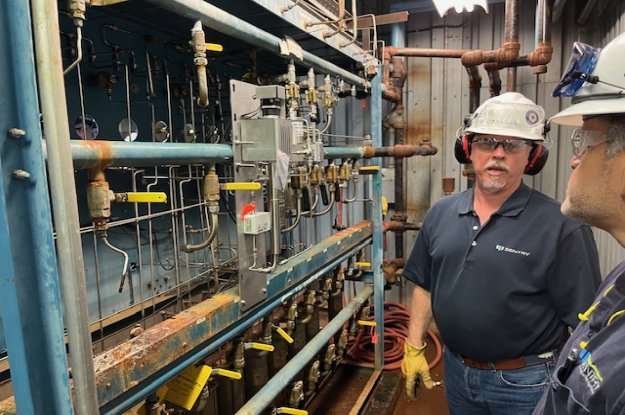
Power Generation
CASE STUDY: Replace Your SWAS Panels
In terms of total annual net electricity generation, this power plant is ranked #44 out of 11,979 power plants nationwide.
Read More
Power Generation
Do You Trust Your Process Analytics?
Accurate sampling all depends on regular maintenance. Are you maintaining the critical instruments that your plant relies on?
Read More
Protect Your SWAS
Sentry's sampling accessories ensure that you can maintain precise temperatures and/or pressures.