Commercial power plant operations frequently require cycling from off to on and varying load states of all plant design types.
These cycling operations create thermal and mechanical stresses that disrupt the protective layer on the boiler tubing and key components. This type of operation can lead to erosion and corrosion, adding particulate to the system.
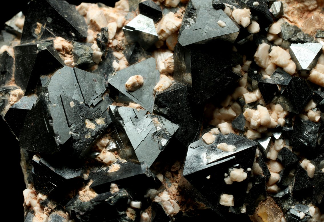
These materials consist of metals and metal oxides, primarily iron and iron oxides (magnetite and hematite). These magnetite particles can damage a plant’s steam and water analysis system (SWAS) by plugging sample conditioning components and analyzers.
Preventing magnetite from plugging your swas
Operators strive to keep plants online and operating when there’s demand to generate revenue, and at lower capacity or offline when the reverse is true. This creates “cycling” that plants weren’t specifically designed for, which can cause thermal stresses and chemistry changes. These issues can lead to iron or magnetite in the sample, which causes pressure drops, flow suppression and equipment damage.
When magnetite is excessive, cycle chemistry isn’t enough. Operators need to physically remove the magnetite to protect the steam and water conditioning components and analyzers and, ultimately, the plant.
Proper equipment can help mitigate magnetite build-up issues. Blowdown valves and magnetite traps are particularly helpful in preventing magnetite from plugging a steam and water analysis system.
High Pressure Blowdown Valves (HPBVs) - The best method for removing deposits in the sample lines and protecting coolers and conditioning equipment are blowdown valves. From the point of extraction all the way through the panel, an HPBV can purge any contaminants from the line to keep samples lines clear.
HPBVs are typically arranged with an isolation valve between the sample line and a blowdown header that’s routed to a drain or tank arrangement prior to temperature or pressure reduction. Blowdown discharge must not be restricted, as this can impart a backpressure - cross-contamination with higher pressure samples backing up into lower pressure sample lines. Since there’s no pressure reduction or sample flow meter, purging velocity is not metered or controlled.
Magnetic Traps - These traps use high-strength magnets to isolate and remove corrosion products (such as magnetite particulates) from the sample stream to protect sample conditioning and analytical instruments from critical downtime and costly repairs.
In combined cycle plants or any plant that cycles, removal of magnetite is essential. Samples of particular concern in Heat Recovery Steam Generator (HRSG) plants are HP and IP drum samples, which are notoriously high in magnetite. For conventional plants, boiler drum water and continuous blowdown samples are strong candidates for traps.
As an iron oxide, magnetite is attracted to magnets. When the sample flows past the magnetic surface, the magnets attract and capture the magnetite. An important distinction of a magnetic trap is that it only traps magnetic particulate which are typically present in the largest quantities and particle size. Additionally, if there’s non-magnetic particulate in the sample stream, it will flow uninterrupted through the trap to the downstream components.
Magnetic traps, theoretically, won’t plug lines or prevent flow to downstream components. When not properly cleaned and maintained, they simply become “loaded,” meaning the magnet can’t attract additional magnetite until the particulates are flushed out. Magnetic traps are equipped with a flush handle to easily purge trapped magnetite from the line.
However, unless they’re designed with the appropriate magnets, magnetic traps typically have temperature limitations. For example, a standard neodymium magnet permanently degrades at 175°F (79°C).
Fortunately, magnetic traps are commercially available for use in both low- and high- pressure applications, protecting both the sample conditioning equipment and the analyzers.
Early magnetic traps utilized low-pressure designs that couldn’t protect the pressure control valve (PCV or VREL) and usually featured direct contact of the magnetite with the magnet, making maintenance and cleaning difficult. Newer designs, however, separate the magnet from the magnetite by a steel shield. They’re also pre-valved for backflush, making implementation and use simple and user-friendly. Visual verification of a clean sample (flush water) to the sink is recommended.
The magnetic trap is typically located upstream of the PCV, where most particulate lodges. Implementation improves flow consistency for cycling plants and improves reliability of downstream components, such as thermal shutoff devices for which magnetite may have intermittent effects (attraction to magnetic fields for solenoid-based systems or lodging in mechanical systems).

Written by John Powalisz
John Powalisz, Director of International Sales, is dedicated to sharing his technical expertise and knowledge of sampling equipment and systems in power plants, refineries, chemical and food processing facilities garnered from more than 19 years with the company. John has worked with clients worldwide to help them to comply with regulations and optimize processes by applying proper sampling hardware and techniques. While he is well-versed in all Sentry products and applications, he is particularly focused on the food and beverage and power generation markets as well as emerging market development.
Related Posts

Power Generation
CASE STUDY: Replace Your SWAS Panels
In terms of total annual net electricity generation, this power plant is ranked #44 out of 11,979 power plants nationwide.
Read More
Power Generation
Do You Trust Your Process Analytics?
Accurate sampling all depends on regular maintenance. Are you maintaining the critical instruments that your plant relies on?
Read More
Power Generation
Cation Conductivity vs. Specific Conductivity
Conductivity is useful as a general measure of stream water quality. Each stream has a relatively constant range of conductivity. Once a baseline is established, it can be compared with regular conductivity measures.
Read More